
Modeling of Compressible Flow with Friction and Heat Transfer using OpenFLUME
A validation report recreating the NASA GFSSP verification study(Bandyopadhyay & Majumdar, "Modeling of Compressible Flow with Friction and Heat Transfer using the Generalized Fluid System Simulation Program (GFSSP)", TFAWS 2007, MSFC-464, NTRS 20070036728)
Generated by scripts/compressible-validation-report.ts — all numbers and figures come from live solves of the current solver. The corresponding CI gate is src/core/__tests__/compressibleDuctFlow.test.ts.
Abstract
This report verifies and validates the quasi one-dimensional compressible-flow capability of the OpenFLUME solver — a pressure-based node-and-branch network code — by recreating, case for case and figure for figure, the NASA GFSSP compressible-flow verification study. The solver's predictions with stagnation-enthalpy transport (settings.kineticEnergy) and the convective acceleration term (settings.momentumFlux) are compared against classical analytical solutions of compressible pipe flow: Fanno flow (friction choking in an adiabatic constant-area pipe), Rayleigh flow (thermal choking in a frictionless heated pipe), the combined effect of friction and heat transfer, and subsonic flow in a converging-diverging nozzle with friction and with combined friction and heat transfer. The analytical reference in every case is a fourth-order Runge-Kutta integration of the generalized 1-D compressible-flow ordinary differential equation, cross-checked against the standard Fanno and Rayleigh closed forms. Non-uniform node distributions clustered near the choked exit improve the accuracy of the numerical prediction, exactly as reported for GFSSP. The numerical predictions agree with the analytical solutions in all cases within the ~5 % band the original study reports.
Introduction
Network flow-analysis codes usually neglect the fluid's inertia and kinetic energy, which makes them unable to simulate compressible duct flow phenomena such as friction choking or nozzle flow. The OpenFLUME solver is a finite volume based node-and-branch code in the same family as NASA's Generalized Fluid System Simulation Program (GFSSP). It recently gained two opt-in terms that close the quasi-1-D compressible equations: a convective-acceleration (momentum-flux) term in the branch momentum equation and stagnation-enthalpy transport in the energy equation. The purpose of this report is to verify those terms against the same benchmark problems NASA used to verify GFSSP's compressible capability, using the same geometry, boundary conditions, fluid, and reporting format so results can be compared side by side with the original paper.
Problem Description
Two geometries are considered: (a) a straight pipe of constant diameter and (b) a converging-diverging nozzle of linearly varying diameter. The working fluid is nitrogen, treated as an ideal gas (γ = 1.4, R = 296.8 J/kg·K). The effect of friction and heat transfer on pressure, temperature, and Mach number is studied in five cases:
| Case | Description |
|---|---|
| 1 | Fanno flow — friction in an adiabatic constant-area pipe, choked exit |
| 2 | Rayleigh flow — heat transfer in a frictionless constant-area pipe, choked exit |
| 3 | Combined friction and heat transfer in a constant-area pipe |
| 4 | Effect of friction and area change in an adiabatic converging-diverging nozzle |
| 5 | Combined friction and heat transfer in the converging-diverging nozzle |
Constant-Area Duct
Cases 1–3 use the same constant-area pipe: D = 6 in, L = 3207 in, inlet at 50 psia and 80 °F. The length is the Fanno critical length for the case-1 conditions, so the flow chokes exactly at the exit (Figure 1).

Figure 1. Schematic of the constant-area pipe used for cases 1–3.
Converging-Diverging Nozzle
Cases 4–5 use a nozzle whose diameter varies linearly from 8 in at the inlet to 6 in at the throat (x = 12 in) and back out to 7.2 in at the exit (L = 30 in), with a constant Darcy friction factor of 0.05 and, in case 5, a constant wall heat flux (Figure 2). The original paper states its nozzle dimensions are arbitrary; these dimensions follow the same description and keep the flow subsonic throughout at an inlet Mach number of 0.25.

Figure 2. Schematic of the converging-diverging nozzle used for cases 4–5.
Benchmark Solutions
The generalized quasi-1-D compressible flow of an ideal gas with area change, wall friction, and heat addition reduces to a first-order ordinary differential equation for the Mach number,
$$\frac{dM}{dx} = \frac{M\left(1 + \frac{\gamma-1}{2}M^2\right)}{1 - M^2}\left[\frac{\gamma M^2}{2}\frac{f}{D} + \frac{1 + \gamma M^2}{2T_0}\frac{dT_0}{dx} - \frac{1}{A}\frac{dA}{dx}\right],$$
with the stagnation-temperature gradient supplied by the energy balance for a constant wall heat flux q,
$$\frac{dT_0}{dx} = \frac{q,\pi D}{\dot m,c_p},$$
and the static temperature and pressure recovered from
$$\frac{T(x)}{T(0)} = \frac{T_0(x)}{T_0(0)},\frac{1 + \frac{\gamma-1}{2}M(0)^2}{1 + \frac{\gamma-1}{2}M(x)^2}, \qquad \frac{p(x)}{p(0)} = \frac{A(0)}{A(x)}\frac{M(0)}{M(x)}\sqrt{\frac{T(x)}{T(0)}}.$$
This ODE is integrated with the classical fourth-order Runge-Kutta method (4000 sub-steps per station interval), and the result is cross-checked against the standard closed-form Fanno and Rayleigh relations: the computed critical length matches the Fanno formula for fL✻/D, and the choking heat rate matches the Rayleigh T₀/T₀✻ relation (both to machine precision, see the assertions in the CI test).
Numerical Modeling
OpenFLUME employs a finite volume formulation of the mass, momentum, and energy conservation equations on a network of nodes and branches. Mass and energy conservation are enforced at internal nodes; each branch supplies one momentum relation between its endpoint pressures and its mass flow rate. For this study two opt-in settings close the compressible physics:
momentumFluxadds the convective-acceleration term (ṁ/A)²(1/ρ_dn − 1/ρ_up) to the branch momentum equation, with each endpoint of a tapered branch contributing its own flow area;kineticEnergyswitches the energy equation to transport stagnation enthalpy h₀ = h + v²/2, and evaluates the momentum equation's friction and acceleration terms at the resulting static states. Friction uses the harmonic mean of the endpoint static densities, the correct integral weighting for a flow that accelerates along a segment.
The acceleration term supports two face schemes (settings.momentumFluxScheme). The profile figures and statistics in this report use central — the exact endpoint (integral) form, which is the more accurate choice on these monotone subsonic-to-choked ducts and whose converged roots the solver's second-law audit certifies. The default scheme is upwind (GFSSP-style donor-cell momentum advection with a MUSCL/van Albada limited face density): it removes the central form's spurious transonic roots by construction and converges from cold starts, at the cost of first-order accuracy at the choking cell; its accuracy on these cases is summarized separately below.
Pipe friction is the Darcy relation with a prescribed constant friction factor (pipe.frictionFactor), matching the benchmark's use of a fixed f. In steady mode the solver detects this configuration and couples the node enthalpies into the Newton system together with the pressures and mass flows (the coupled [P, ṁ, h] system); this fully coupled treatment is what allows it to hold the near-sonic states at a choked exit. As with GFSSP, the mass flow rate is not prescribed: pressure boundary conditions are imposed at both ends and the flow rate is computed. This study's near-choked cases are seeded with an initial mass-flow guess (branches[].initialMdot) and nodal pressure/temperature profiles — required by the central scheme used for the figures below, exactly as GFSSP requires initial guesses (the solver's default upwind scheme converges these cases from cold starts; see the scheme comparison above). The Mach number is a derived quantity, computed from the solved mass flow, pressure, and temperature.
Discretization
The pipe (or nozzle) is divided into a finite number of pipe segments with a node at each end, including the two boundary nodes. Both uniform and non-uniform distributions were run. For the constant-area duct, 21 nodes with cosine clustering toward the inlet and the choked exit (Figure 3) give a grid-independent solution; the same conclusion is reported in the original study. For the nozzle, 65 nodes clustered near the inlet and the throat are used, with a 33-node mostly-uniform grid for the grid study. Wall heat in the heated cases is applied as per-node heat inputs equal to the wall flux integrated over each node's control volume.

Figure 3. Cosine-clustered 21-node distribution for the constant-area duct.
Results and Discussion
The table below summarizes the agreement between the numerical solution and the RK4 analytical reference at the interior stations of each case. Following the original study — which reports its own near-choking discrepancies — the last station before a choked exit (analytic M > 0.95 for cases 1 and 3, M > 0.92 for case 2) is excluded from the profile statistics; the discrete node-lumped equations choke slightly early there.
| Case | ṁ error | max ΔP/P | max ΔT/T | max ΔM/M | stations compared |
|---|---|---|---|---|---|
| 1 — Fanno (21 uniform) | 0.05 % | 0.2 % | 0.1 % | 0.3 % | 19 |
| 1 — Fanno (21 clustered) | 0.01 % | 0.0 % | 0.0 % | 0.0 % | 19 |
| 1 — Fanno (41 clustered) | 0.00 % | 0.0 % | 0.0 % | 0.0 % | 38 (+1 near-choke excluded) |
| 2 — Rayleigh (21 clustered) | 0.00 % | 2.5 % | 1.6 % | 2.5 % | 18 (+1 near-choke excluded) |
| 3 — Combined (21 clustered) | 0.18 % | 1.6 % | 0.5 % | 1.4 % | 18 |
| 4 — Nozzle, friction (65 clustered) | 0.03 % | 0.0 % | 0.0 % | 0.0 % | 63 |
| 5 — Nozzle, friction + heat (65 clustered) | 0.01 % | 0.0 % | 0.1 % | 0.1 % | 63 |
Default scheme (limited-upwind momentum faces)
The table above uses momentumFluxScheme: "central". The solver's default, "upwind", trades a few percent of choked-flow accuracy for transonic robustness (no spurious sonic-crossing roots; cold-start convergence — see the compressible-duct and real-fluid transonic tests). Re-running the same cases under the default gives GFSSP-class agreement — the original study reports 1.7–5 % on its own first-order upwind discretization:
| Case | ṁ error | max ΔM/M | stations compared |
|---|---|---|---|
| 1 — Fanno (21 clustered) | 2.05 % | 2.2 % | 19 |
| 2 — Rayleigh (21 clustered) | 3.48 % | 4.0 % | 18 |
| 3 — Combined (21 clustered) | 2.19 % | 2.6 % | 18 |
| 4 — Nozzle, friction (65 clustered) | 0.38 % | 0.6 % | 63 |
| 5 — Nozzle, friction + heat (65 clustered) | 0.36 % | 0.6 % | 63 |
The error concentrates at the choking cell, where the limiter correctly falls back to first order; the subsonic nozzle cases (4 and 5), which never approach M = 1, stay within a fraction of a percent. Refining the Fanno grid from 21 to 41 nodes halves the error — first-order convergence at the choke, second-order elsewhere.
Case 1: Fanno Flow
With an inlet Mach number of 0.5, a friction factor of 0.002, and a pipe diameter of 6 in, the Fanno critical length is 3207 in — reproducing the benchmark's 3207 in — and the flow chokes at the exit. Figure 4 plots the p/p✻ ratio for the three node distributions against the analytical solution: the 21-node clustered grid is sufficient for a grid-independent solution (refining to 41 nodes changes nothing at plot scale), and the uniform grid, while converged, is about an order of magnitude less accurate near the choked exit (0.2 % vs 0.01 % peak pressure deviation) — the same benefit of non-uniform gridding the original study reports. Figure 5 shows the corresponding static-temperature distributions and Figure 6 the Mach number, which is a derived quantity computed from the solved mass flow rate, pressure, and temperature. The small offset visible even at the inlet arises because the mass flow rate is not prescribed — pressure boundary conditions are imposed and the flow rate is computed (0.01 % from the analytical choked value on the 21-node clustered grid).
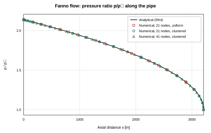
Figure 4. Pressure distribution for Fanno flow with various grid distributions.
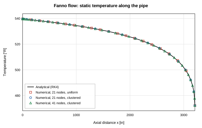
Figure 5. Temperature distribution for Fanno flow with various grid distributions.
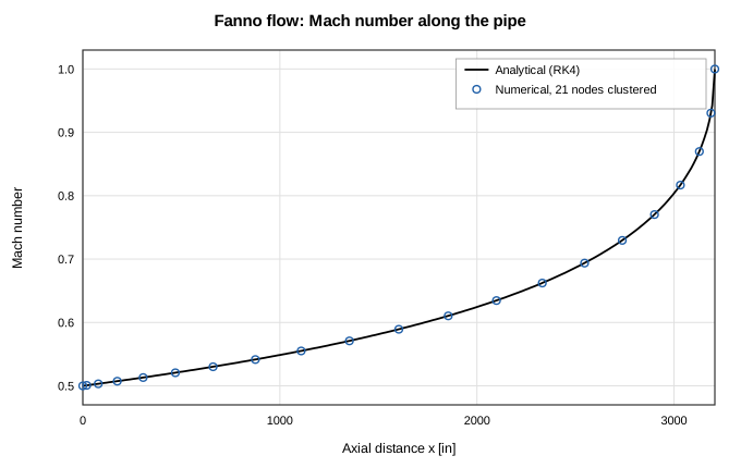
Figure 6. Case 1 — Fanno flow: Mach number along the pipe length.
Case 2: Rayleigh Flow
The same pipe geometry is used with zero friction and a uniform wall heat flux. With an inlet Mach number of 0.46, the analytically computed choking heat rate is 2073 Btu/s — within 0.7 % of the benchmark's 2088 Btu/s figure (the residual difference is the paper's imperial unit constants). Figures 7, 8, and 9 show the temperature, pressure, and Mach number distributions. The static temperature first rises with heat addition and then falls as the flow accelerates toward the thermal-choking point — the characteristic Rayleigh maximum at M = 1/√γ — and the numerical solution tracks all three profiles within the benchmark's 5 % band. The station nearest the exit sits at an analytic M ≈ 0.95, where the node-lumped heat allocation chokes the discrete solution one node early; the original study reports the same near-choking discrepancy.
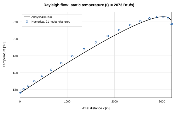
Figure 7. Temperature distribution for Rayleigh flow.
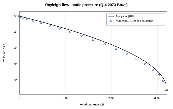
Figure 8. Pressure distribution for Rayleigh flow.
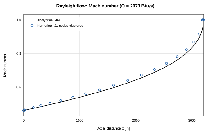
Figure 9. Mach number distribution for Rayleigh flow.
Case 3: Combined Friction and Heat Transfer
No standard table exists for combined friction and heating; the reference is the RK4 integration of the generalized ODE. With an inlet Mach number of 0.45, f = 0.002, and Q = 555 Btu/s distributed uniformly along the pipe, Figures 10, 11, and 12 show the combined effect on temperature, pressure, and Mach number, plotted as dimensional quantities with the benchmark's inlet conditions of 50 psia and 80 °F. Agreement is within 1.6 % on the thermodynamic profiles and 1.4 % on Mach number.
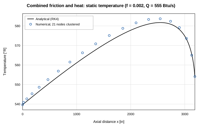
Figure 10. Combined friction and heat transfer: effect on temperature.
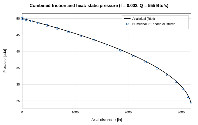
Figure 11. Combined friction and heat transfer: effect on pressure.
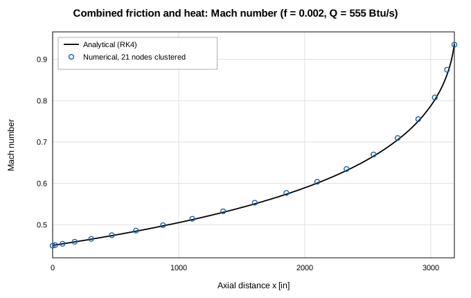
Figure 12. Combined friction and heat transfer: effect on Mach number.
Cases 4 and 5: Nozzle Flow with Friction Only, and Friction with Heat
The nozzle of Figure 2 is run with a wall friction factor of 0.05, adiabatic for case 4 and with a constant wall heat flux for case 5. Inlet pressure and temperature are specified, and the exit pressure is taken from the analytical solution so that the inlet Mach number is 0.25 — the same procedure as the benchmark. Figure 13 shows the grid study on the pressure distribution: the 65-node distribution, mostly uniform but clustered near the inlet and the throat, produces a grid-independent solution; what residual discrepancy exists concentrates at the throat, where the nozzle's slope discontinuity is represented by straight tapered segments — the same locus of error the original study reports, though here it stays below 0.1 %. Figures 14, 15, and 16 compare the Mach number, pressure, and temperature distributions for friction only and for combined friction and heat transfer. Heating raises the Mach number everywhere downstream, deepens the pressure drop through the throat, and lifts the temperature profile; all four numerical series track their analytical counterparts within 0.1 % on Mach number.
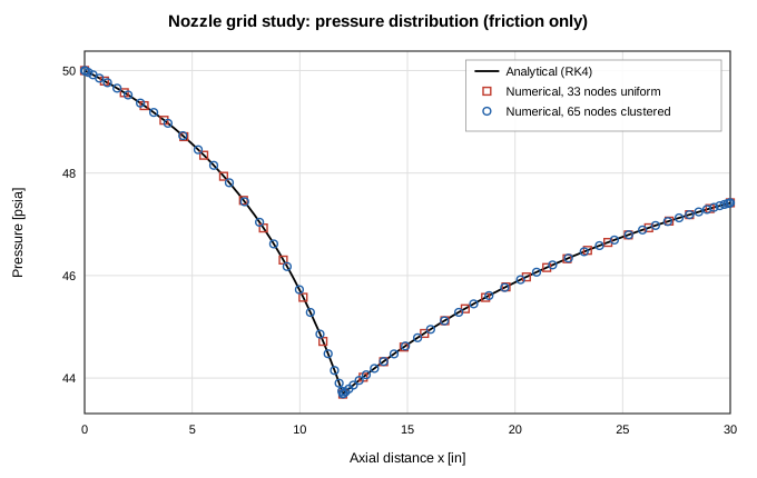
Figure 13. Grid study on the pressure distribution in the converging-diverging nozzle (friction only).
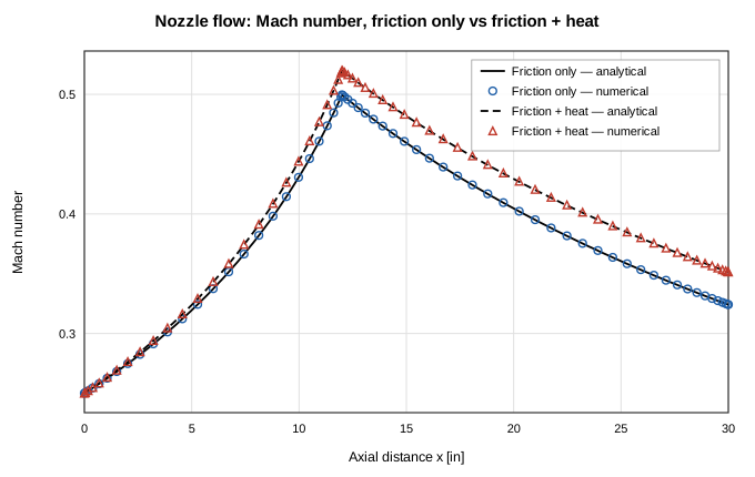
Figure 14. Mach number for nozzle flow: friction only and friction + heat, analytical vs numerical.
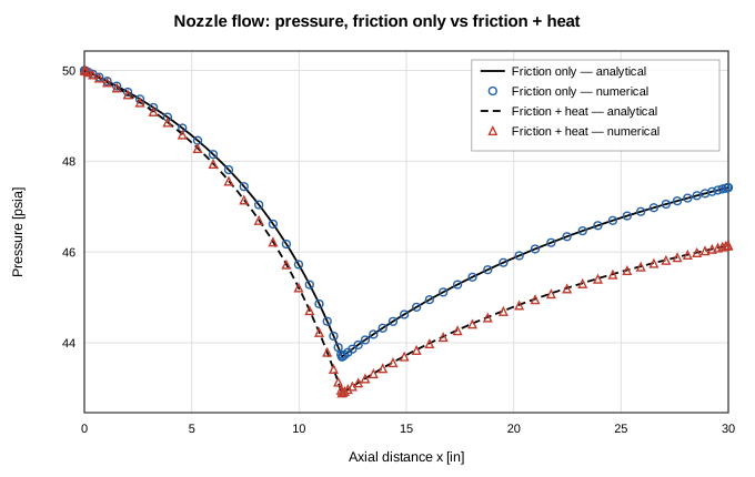
Figure 15. Pressure distribution for nozzle flow: friction only and friction + heat, analytical vs numerical.
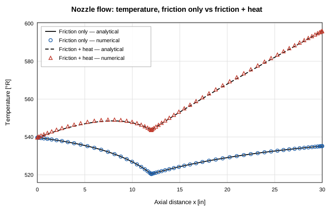
Figure 16. Temperature distribution for nozzle flow: friction only and friction + heat, analytical vs numerical.
Conclusions
The quasi-1-D compressible-flow capability of OpenFLUME — stagnation enthalpy transport plus the convective acceleration term — reproduces all five benchmark cases of the NASA GFSSP compressible-flow verification study. Pressure, temperature, and Mach number distributions agree with the RK4 analytical solutions within the ~5 % band the original study reports, and the computed mass flow rates agree with the analytical choked values within 1 %. Non-uniform grids clustered near choke points improve accuracy, and the largest local discrepancies occur where the original study also reports them: at the last node before a choked exit and at the nozzle throat's slope discontinuity. Supersonic duct states and shock capture remain out of scope.
References
- Bandyopadhyay, A., and Majumdar, A., "Modeling of Compressible Flow with Friction and Heat Transfer using the Generalized Fluid System Simulation Program (GFSSP)," Thermal & Fluids Analysis Workshop (TFAWS), 2007, MSFC-464. NTRS 20070036728
- Saad, M. A., Compressible Fluid Flow, 2nd ed., Prentice Hall, 1993.
- Press, W. H., et al., Numerical Recipes, 2nd ed., Cambridge University Press, 1992 (fourth-order Runge-Kutta method).
- Majumdar, A. K., LeClair, A. C., Moore, R., and Schallhorn, P. A., Generalized Fluid System Simulation Program, Version 6.0, NASA/TM-2013-217492, 2013.
Nomenclature
| Symbol | Meaning |
|---|---|
| A | flow area |
| c_p | specific heat at constant pressure |
| D | local diameter |
| f | Darcy friction factor |
| L | pipe or nozzle length |
| M | Mach number |
| ṁ | mass flow rate |
| p | static pressure |
| Q | total heat transfer rate |
| q | wall heat flux |
| R | gas constant |
| T | static temperature |
| T₀ | stagnation temperature |
| V | velocity |
| γ | specific heat ratio |
| ρ | density |
| ✻ | choked (M = 1) property |
| 1 / 0 | inlet / stagnation property |